


What are the performance indicators for the power cable?
1. Purpose of the power cable
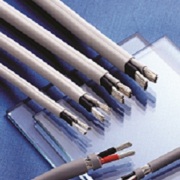
The power cable is the wire that transmits the current. Usually the way the current is transmitted is point-to-point transmission.
Power cable according to the use can be divided into AC AC power cable and DC DC power line, usually AC power line is through the high voltage of the AC wire, this type of wire due to the need for uniform high voltage standard safety certification can be formally produced.
DC line is basically through the lower voltage of the DC, so the safety requirements and no AC line strict, but for safety reasons, the current countries or require a unified safety certification.
2. Performance of twisted pair in power cable
For twisted pair, the user is most concerned about the performance of several indicators of its performance. These indicators include attenuation, near-end crosstalk, impedance characteristics, distributed capacitance, DC resistance and so on.
(1) attenuation
The attenuation is measured along the link's signal loss. The attenuation is related to the length of the cable, and as the length increases, the signal attenuation increases. Attenuation with "db" as a unit, said the source transmitter signal to the receiver signal strength ratio. Since the attenuation varies with frequency, the attenuation at all frequencies within the application range should be measured.
(2) Near-end crosstalk
The crosstalk is near-end crosstalk and far-end crosstalk (FEXT). The tester mainly measures NEXT. Due to the presence of line loss, the effect of FEXT is less affected. Near-end crosstalk (NEXT) loss is measured in a UTP link from a pair of lines to another line of signal coupling.
For UTP links, NEXT is a key performance metric and an indicator of the most difficult to measure. As the signal frequency increases, the measurement difficulty will increase. NEXT does not represent the crosstalk value generated at the near endpoint, it simply represents the crosstalk value measured at the near endpoint.
This value will vary with the length of the cable, the longer the cable, the smaller the value becomes. At the same time the signal at the sending end is also attenuated, and the crosstalk to the other pairs is relatively small.
Experiments show that only within 40 meters measured NEXT is more real. If the other end is more than 40 meters of information outlet, then it will produce a certain degree of crosstalk, but the tester may not be able to measure the crosstalk value.
Therefore, it is best to perform NEXT measurements at both endpoints. Now the tester is equipped with the appropriate equipment, so that at the end of the link will be able to measure the two ends of the NEXT value.
(3) DC resistance
TSB67 does not have this parameter. DC loop resistors consume a portion of the signal and turn it into heat. It refers to the sum of a pair of wire resistors,
11801 specifications of the twisted pair DC resistance shall not be greater than 19.2 ohms. The difference between each pair can not be too large (less than 0.1 ohms), otherwise it means poor contact, you must check the connection point.
(4) characteristic impedance
Different from the loop DC resistance, the characteristic impedance includes the resistance and the frequency of 1 ~ 100MHz inductance and capacitance impedance, which is the distance between a pair of wires and the electrical properties of the insulator.
Various cables have different characteristic impedances, while twisted pair cables have 100 ohms, 120 ohms and 150 ohms.
(5) attenuation crosstalk ratio
In some frequency ranges, the proportional relationship between crosstalk and attenuation is another important parameter that reflects cable performance. ACR is also expressed in terms of signal-to-noise ratio (SNR: Signal-Noiceratio)
It is calculated by the difference between the worst attenuation and the NEXT magnitude. ACR value is larger, that anti-interference ability is stronger. General system requirements are at least 10 dB.
(6) cable characteristics
The quality of the communication channel is described by its cable characteristics. The SNR is a measure of the strength of the data signal in consideration of the interference signal. If the SNR is too low,
Will cause the data signal to be received, the receiver can not distinguish between the data signal and noise signal, and ultimately lead to data errors. Therefore, in order to limit the data error to a certain extent, a minimum acceptable SNR must be defined.
The above is the power cable performance indicators of the introduction, more on the power cable content, please pay attention to kingsignal official website.


- Jiangsu Webest Micro-electronics Co., Ltd.
- AVIC——KS (Yingkou) Technology Co., Ltd.
- Mianyang Kingsignal Electronics Technology Co., Ltd.
- Shaanxi Electronics Technology Co., Ltd
- Wuhan Kingsignal Opto-Electronics Co., Ltd.
- Changsha Kingsignal Defence Technology Co., Ltd.
- Linkoncept Transportation Communication System (Changzhou) Co., Ltd.
- Changzhou PC Specialties Co.,Ltd.
- Changzhou Kingsignal Fengshi Communication Equipment Co., Ltd.
- Xinfeng Kingsignal PC Specialties Technology Co., Ltd.
- Ganzhou Photon Signal Conduction Technology Co., Ltd.
- Kingsignal Optical Fiber and Cable (Ganzhou) Co., Ltd.
- Ganzhou Kingsignal Cable Technology Co., Ltd.
- Advanced Interconnect Resource Co., Ltd.
- Dongguan Kingsignal Electronics Co., Ltd.
- Longgang R&D and Production Base of Shenzhen Kingsignal
- Dongguan kingsignal Electronics
- Kingsignal Brazil limited
- Kingsignal high technology (Thailand)
- Jinnuo (Tianjin) business factory
Copyright © 2026 Kingsignal Technology Co., Ltd. All rights reserved.粤ICP备17109779号